ajdelange wrote:RE the diagram in the previous post: Perhaps I'm misunderstanding the application but there is nothing behind 5-6 and 7-8 except a pair of contacts. If you intend that the things that appear to be outlets in the diagram be energized when those contacts close then one side of each contact pair must be energized. One way to make that happen , assumning the black (hot wire) from the line cord jumper is connected to pin 1, is to jumper 1 to 5 to 7. Then connect 6 to the hot side (copper colored screw head) of one outlet and 8 to the hot side of the other outlet. Connect the neutral sides of the outlets (silver colored screw head) to pin 2 and wire-nut all the earths (grounds - green or green w/yellow stripe - screw head is hex shaped on outlet) together.


ajdelange wrote:RE the diagram in the previous post: Perhaps I'm misunderstanding the application but there is nothing behind 5-6 and 7-8 except a pair of contacts. If you intend that the things that appear to be outlets in the diagram be energized when those contacts close then one side of each contact pair must be energized. One way to make that happen , assumning the black (hot wire) from the line cord jumper is connected to pin 1, is to jumper 1 to 5 to 7. Then connect 6 to the hot side (copper colored screw head) of one outlet and 8 to the hot side of the other outlet. Connect the neutral sides of the outlets (silver colored screw head) to pin 2 and wire-nut all the earths (grounds - green or green w/yellow stripe - screw head is hex shaped on outlet) together.
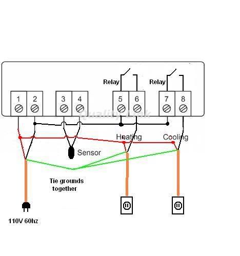

ajdelange wrote:Not quite but closer. Kbar's sketch is OK (except that the white wire is called the neutral and the green wire earth or ground).

Users browsing this forum: No registered users